

Ok so now that we have ironed out the issues with the drawing and made them about as clear as we can I decided to start a new thread with them so they are easy to find without having to dig through all 900 pages of Todd’s book . There are a few people that should be mentioned here and thanked, Dave (Aka. Fitter48093) for the org drawings, Chris (Aka Arai) For his help in confirming and helping this project along and Todd (Aka 6781camaro, Master Blaster) for his help along the way as well. I know that Chris, Todd and I and I'm sure Dave as well when on the forums will be happy to answer any questions that arise.
![Image]()
![Image]()
![Image]()
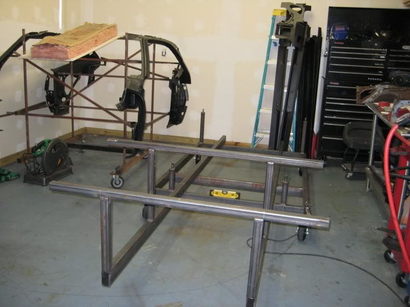
and here's a photo or two of what it should look like. My personal cart.
![Image]()
Cris' cart.
![Image]()
And Todd's show cart.
![Image]()


and here's a photo or two of what it should look like. My personal cart.

Cris' cart.
And Todd's show cart.

 So can this 68 jig work for a 69? If someone knows it will save me some time looking up the factory specs and comparing to the pics Almos (thanks!) posted.


