
I'm sure my installation will differ from other people's but I thought I'd throw what I learned up on the forum for posterity.
This was my first Vintage Air install so I'm a novice. The car is a 1967 non-AC convertible. The front clip was off for engine swap, etc. I took the dash all apart so that I could repaint it after cutting vents in, install new firewall pad, and other things.
A one-line summary: of each of my findings is provided below. A full discussion of each follows.
I had a few goals for my installation (and my restoration in general). This was to be a resto-mod whereby new technology had to look stock. Therefore, I was adamant that I wanted no aftermarket controls or vents and I wanted to make the underhood installation look as tidy as possible.
There are other threads on the forum that helped me realize that others had already figured out how to install a VA system by routing the houses through the kickpanel, cowl, blower motor hole, and inner fender well instead of directly out the firewall bulkhead. This info helped me and pointed me to Frank at Prodigy Customs. He was familiar with what I wanted to do and was knowledgeable so I ordered my system from him. At the time I was under the impression that he had some custom bits that he'd provide in order to make this all work. I subsequently found out that everything is available directly from VA. As a side note, I'm not going to bash Frank (he seems popular and he did help me early on and I don't know what his situation is - he might be really busy or something) but I will say that he went completely dark on me a little bit after purchase. No return of e-mails or calls after one post-purchase exchange (more details later). It might just be that he didn't like me but that was my experience, for what it's worth.
Back to the parts... Here is what I purchased:
Truth be told there are a few parts there that I didn't end up using, such as the fresh air caps. And I probably could've ordered the compressor with the proper head and fittings for my installation but more on that later. The key to that list is that it includes the OEM-style center vent and astroball vents, as well as the extra hose and fittings necessary to run the install through the fender.
Another thing to point out is that the Gen IV Evap Kit includes the VA OEM Control Panel Conversion Kit (p/n 475168 for non-AC cars), which is a set of slide pots and wiring that allow the mechanical factory heater control levers to control the new electronic VA ECU for fan, temperature, and diverter. This is a great idea and it works wonderfully. The old levers move like butter compared to when they were attached to rusty old cables and it looks 100% stock. The conversion isn't difficult but it is worth pointing out that your existing controls need to be in operating order. The factory control assembly is made from cheap pot metal and breaks easily. When I pulled mine out of the dash I discovered that a previous owner had fashioned a make-shift repair where mine had broken. This discovery prompted me to consider purchasing a repro AC-style control panel to really complete the OEM look and I called Frank at Prodigy to discuss this. At this point in our relationship, Frank returned my call and, after some difficulty dealing with VA, he was able to convince VA to approve exchange of my non-AC ECU for an AC ECU. It turns out that they are different so order accordingly. If you plan to install the system into a non-AC car but use an OEM AC control panel then you probably need to tell them so you get the proper ECU. In the end, however, I was able to source an intact used non-AC heater control from a friend for very little money so I didn't end up doing the ECU exchange. For what it's worth, I tried to notify Frank of this (as well as ask further questions later) but was never able to reach him again.
![Image]()
The only lame thing about the VA control conversion kit is how they attempt to re label the panel. They give you a sticker that you're supposed to apply over the OEM panel. This requires additional disassembly (bending pot metal tabs that break and then require screws to reattach) and IMHO looks like crap. It isn't transparent for proper nighttime illumination and it has a "VintageAir" logo in the center. I didn't deem it worthwhile since it ruins the OEM look and the only benefit it provides is renaming the lowest "Off/Defroster/De-Ice" lever to "DASH/FLR/DEF" (the Fan and Temp levers don't change functionality) so I left mine alone. One other thing to point out about the OEM control conversion setup is that the potentiometers need to be re calibrated every time the battery is disconnected (or power to the VA evap ECU is lost). This is easy enough (levers to off, key on, levers to full, ground a little "programming lead" on the evap unit, wait a couple secs, key off) but you need to keep access to the programming lead handy and remember to do it.
![Image]()
Next on the OEM front is the vents. The gen IV kit comes with two round vents and a rectangular center vent and they expect you to drill your dash for the round ones and cut the dash and decorative center dash panel for their aftermarket vents, This is simple and economical but not the look I was striving for. IMHO, the outer round vents aren't horrible but the center vent looks like crap. It's too small for the space and just looks aftermarket. There is no way that I would ever consider not using the OEM center vent. It is available and, when used with a new AC-style center dash decorative panel, looks very factory installed. The only caveat to the OEM center vent is that it comes in two pieces that aren't held together in any way. It also includes two notched rubber pieces that are necessary to tighten up the rotating vent portion and prevent rattling. The trick is to figure out how to get it all assembled into one tight unit. The piece that a factory installation uses behind the vent is not a part of the VA kit. It just includes a plastic vent adaptor that allows connection of the round duct to the rectangular vent. I ended up using 3M weatherstrip adhesive to glue the rubber pieces to the side of the OEM vent assembly and fashioned two brackets out of aluminum that forced them down and to the sides to hold the rotating portion in place. This worked well on the workbench and allowed the adhesive to bound really well but I later discovered that they interfered with proper installation of the vent assy into the dash so I eventually had to remove my brackets. Fortunately, by then the notched rubber bits where securely attached and the vent rotates with perfect friction and no rattles. While the OEM center vent is a no brainer to me, the outer "astro ball" vents are a lot harder to install than the simpler aftermarket vents supplied by VA. You can install the aftermarket vents by just using a holesaw but the OEM vents require cutting more complex-shaped holes in the dash. And there is very little margin for error. Very little. The OEM dash bezels have very small (maybe a sixteenth of an inch) lip around the sides where they sit on the dash. Add that precision to the fact that the dash is curved, the hole is oval, and the bezel only fits flush if positioned absolutely perfectly on the dash and you have a real challenge on your hands. I can't profess to knowing the best approach. I used a drill, a nibbler, a pneumatic jigsaw, a Dremel, files, etc. and didn't get it perfect. While I didn't cut too big (thank goodness), I find that the vent bezels don't fit perfectly flush with the dash. This was exacerbated by the fact that the plastic chrome finish extends to the portion of the vent that is behind the dash and reflected any light visible in the gap. Therefore I painted the behind-the-dash portion of the vent flat black and the result is acceptable. By the way, the astroballs provided by VA have reducers that adapt them to the hose size used by the VA unit. One other tip: don't cut the templates out of the manual directly. Photocopy the pages first (making sure that you get a 100% size copy) and cut the copies. You might need to use more than one because they are tough to position properly on the dash the first time.
![Image]()
![Image]()
![Image]()
Speaking of templates, let's move on to mounting the evaporator under the dash. The unit is held by one bolt through the firewall where one of the heater box bolts used to be and a bracket that screws into the cowl near the right-side wiper arm area. They provide a template for where to drill the holes for the cowl bracket. This template indexes off the radio support bracket. Don't use it. I did and the holes ended up being half an inch offset from where I needed them and I felt like an idiot with two new holes in my cowl. Instead of using the template, just attach the bracket to the evap, install it under the dash with the bolt through the firewall, level the unit and hold it place while you mark where the cowl bracket actually meets the cowl. In other words, use the actual unit and bracket as the template. While mentioning this, let me point out that I had the evap in and out many, many times for test fittings, hose routings, firewall
pad replacement, etc. When moving the evap unit around, be careful of the drain elbow on the bottom of the unit. It is only glued on and breaks off easily. I had to epoxy mine back on. Also, note that some of the hardware (bolts/rivets/washers) on the front side of the evap unit is silver. You end up seeing a pretty good portion of the front of the evap under the dash. Take the time to mask and spray those bits satin black. Back to the cowl mount... because I now had two unwanted holes, and had already painted my exterior cowl so didn't want to weld them up, I welded two 10-28 button head bolts to a small strip of metal and dropped in into the properly drilled holes from the outside of the cowl, with some body gap caulk underneath. This solved two issues. First, the strip of metal covered and sealed the extra holes. Second, it allowed me to more easily and repeatedly secure the evap in place using two nuts instead of screws. Speaking of making it easier to secure the evap unit, I also tack welded the firewall bolt to the bracket on the evap unit so that I didn't have to hold a wrench to it under the dash. This made mounting the evap a one-man job.
![Image]()
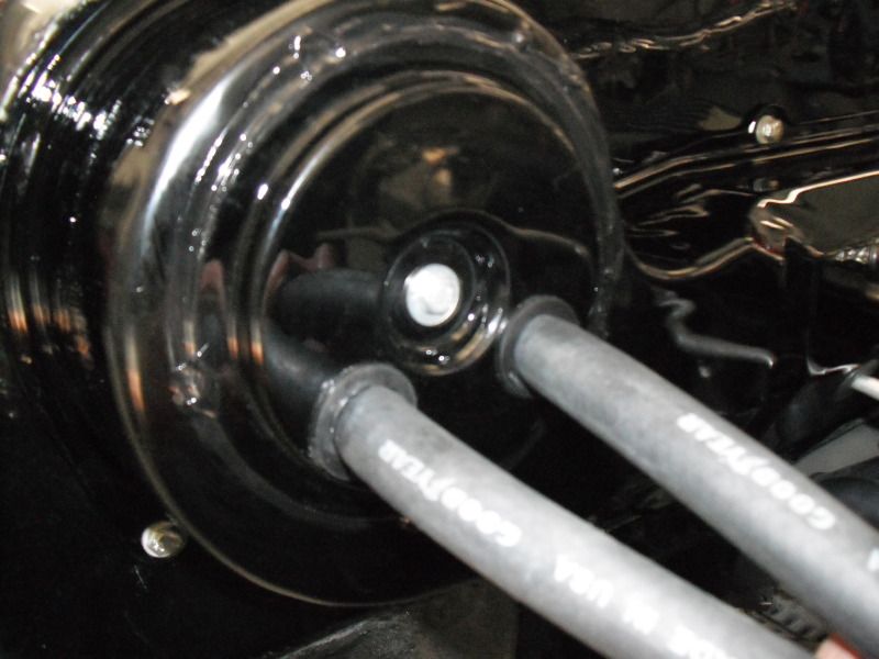
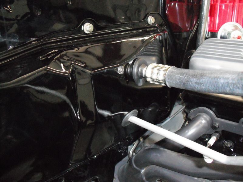
To complete my OEM look, I filled in the holes where the heater core hose fittings came through the firewall and then reinstalled the heater box over the hole in the dash. You can only do this if you're routing the hoses through the kickpanel and cowl because the "normal" VA install uses a bulkhead mounted to the heater core area block-off plate. Speaking of which, if you are routing through the kick panel, you might want to weld a plate over the large hole in the block off plate since you won't be routing anything through it. I also mounted my MSD DIgital 6 Plus onto that plate and covered it with the (vented) heater box but that's an extra customization unique to my installation.
![Image]()
![Image]()
One small issue, the factory defroster vent piece gets replaced by two small, fairly cheap, defroster vent ducts that are mounted via a single screw to the cowl. I found that no matter how I placed them, the stick-on foam that seals them to the dash was visible on one end or the other of each so I had to replace it with new foam that was stuck on a bit further out on each edge.
![Image]()
This was my first Vintage Air install so I'm a novice. The car is a 1967 non-AC convertible. The front clip was off for engine swap, etc. I took the dash all apart so that I could repaint it after cutting vents in, install new firewall pad, and other things.
A one-line summary: of each of my findings is provided below. A full discussion of each follows.
- Can get parts for inner fender well install with factory A/C balls, etc. directly from VA
- Factory control panel pots are great
- ECU is different for non-AC and AC-cars
- Control panel sticker is lame
- Need to re calibrate levers after every battery disconnect
- Need to do something to tighten up OEM center vent
- Buy new A/C center dash panel for OEM look
- Astroball vents come with reducers to fit VA duct hose
- Hard to cut A/C vent holes well and vents don't' sit entirely flush
- Photocopy templates
- Don't use template for upper mounting holes in cowl
- Used studs for upper cowl mount
- Welded firewall mounting bolt to bracket for easier install
- Careful not to break drain hose fitting
- Paint forward facing silver bolts/riviets black
- Heater box can be installed over "blanking plate" for better look
- Stick-on foam on defroster vents needs to be moved so not seen
- Heater hose pipes must be cut or replaced
- Used a straight fitting for large A/C hose
- Comes with way more fittings than you need
- Made my own kickpanel vent "hat" to house hoses and speaker
- Can cover hoses with factory A/C kick panel
- Heater flow control valve solenoid gets hot when energized
- Replaced A/C head and charge fittings to clear Hotchkiss Chassis Max Handlebars
- Trimmed extra ears off compressor in order to clear valve covers and handlebars
- Had to elongate a hole in bracket that mounts to water pump
- Powdercoated mounting brackets
- Binary switch not sufficient if using an electric fan
- Glovebox is small
- Paint on condensor/drier brackets is lame
I had a few goals for my installation (and my restoration in general). This was to be a resto-mod whereby new technology had to look stock. Therefore, I was adamant that I wanted no aftermarket controls or vents and I wanted to make the underhood installation look as tidy as possible.
There are other threads on the forum that helped me realize that others had already figured out how to install a VA system by routing the houses through the kickpanel, cowl, blower motor hole, and inner fender well instead of directly out the firewall bulkhead. This info helped me and pointed me to Frank at Prodigy Customs. He was familiar with what I wanted to do and was knowledgeable so I ordered my system from him. At the time I was under the impression that he had some custom bits that he'd provide in order to make this all work. I subsequently found out that everything is available directly from VA. As a side note, I'm not going to bash Frank (he seems popular and he did help me early on and I don't know what his situation is - he might be really busy or something) but I will say that he went completely dark on me a little bit after purchase. No return of e-mails or calls after one post-purchase exchange (more details later). It might just be that he didn't like me but that was my experience, for what it's worth.
Back to the parts... Here is what I purchased:
- 961167 67-68 Camaro w/o AC Comp kit
- 561167 67-68 Camaro w/o AC gen IV evap kit
- 62566-VCE Plastic fresh air cap
- 62565-VCE 64-72 Chevy/GTO kp fresh cap
- 33137-VUI Grommet large
- 493067-LCA 67-68 Camaro center louver asm
- 49306-VCL Louver kit 67-68 Camaro wo AC OEM
- 04808-VUA Compressor A/C SD-508 134
- 15126-SCA SBC SP PS Comp brkt
- 547001 Extended length hose kit wo drier
- 021067 67-68 Camaro w/wo AC cond w/dr
Truth be told there are a few parts there that I didn't end up using, such as the fresh air caps. And I probably could've ordered the compressor with the proper head and fittings for my installation but more on that later. The key to that list is that it includes the OEM-style center vent and astroball vents, as well as the extra hose and fittings necessary to run the install through the fender.
Another thing to point out is that the Gen IV Evap Kit includes the VA OEM Control Panel Conversion Kit (p/n 475168 for non-AC cars), which is a set of slide pots and wiring that allow the mechanical factory heater control levers to control the new electronic VA ECU for fan, temperature, and diverter. This is a great idea and it works wonderfully. The old levers move like butter compared to when they were attached to rusty old cables and it looks 100% stock. The conversion isn't difficult but it is worth pointing out that your existing controls need to be in operating order. The factory control assembly is made from cheap pot metal and breaks easily. When I pulled mine out of the dash I discovered that a previous owner had fashioned a make-shift repair where mine had broken. This discovery prompted me to consider purchasing a repro AC-style control panel to really complete the OEM look and I called Frank at Prodigy to discuss this. At this point in our relationship, Frank returned my call and, after some difficulty dealing with VA, he was able to convince VA to approve exchange of my non-AC ECU for an AC ECU. It turns out that they are different so order accordingly. If you plan to install the system into a non-AC car but use an OEM AC control panel then you probably need to tell them so you get the proper ECU. In the end, however, I was able to source an intact used non-AC heater control from a friend for very little money so I didn't end up doing the ECU exchange. For what it's worth, I tried to notify Frank of this (as well as ask further questions later) but was never able to reach him again.

The only lame thing about the VA control conversion kit is how they attempt to re label the panel. They give you a sticker that you're supposed to apply over the OEM panel. This requires additional disassembly (bending pot metal tabs that break and then require screws to reattach) and IMHO looks like crap. It isn't transparent for proper nighttime illumination and it has a "VintageAir" logo in the center. I didn't deem it worthwhile since it ruins the OEM look and the only benefit it provides is renaming the lowest "Off/Defroster/De-Ice" lever to "DASH/FLR/DEF" (the Fan and Temp levers don't change functionality) so I left mine alone. One other thing to point out about the OEM control conversion setup is that the potentiometers need to be re calibrated every time the battery is disconnected (or power to the VA evap ECU is lost). This is easy enough (levers to off, key on, levers to full, ground a little "programming lead" on the evap unit, wait a couple secs, key off) but you need to keep access to the programming lead handy and remember to do it.

Next on the OEM front is the vents. The gen IV kit comes with two round vents and a rectangular center vent and they expect you to drill your dash for the round ones and cut the dash and decorative center dash panel for their aftermarket vents, This is simple and economical but not the look I was striving for. IMHO, the outer round vents aren't horrible but the center vent looks like crap. It's too small for the space and just looks aftermarket. There is no way that I would ever consider not using the OEM center vent. It is available and, when used with a new AC-style center dash decorative panel, looks very factory installed. The only caveat to the OEM center vent is that it comes in two pieces that aren't held together in any way. It also includes two notched rubber pieces that are necessary to tighten up the rotating vent portion and prevent rattling. The trick is to figure out how to get it all assembled into one tight unit. The piece that a factory installation uses behind the vent is not a part of the VA kit. It just includes a plastic vent adaptor that allows connection of the round duct to the rectangular vent. I ended up using 3M weatherstrip adhesive to glue the rubber pieces to the side of the OEM vent assembly and fashioned two brackets out of aluminum that forced them down and to the sides to hold the rotating portion in place. This worked well on the workbench and allowed the adhesive to bound really well but I later discovered that they interfered with proper installation of the vent assy into the dash so I eventually had to remove my brackets. Fortunately, by then the notched rubber bits where securely attached and the vent rotates with perfect friction and no rattles. While the OEM center vent is a no brainer to me, the outer "astro ball" vents are a lot harder to install than the simpler aftermarket vents supplied by VA. You can install the aftermarket vents by just using a holesaw but the OEM vents require cutting more complex-shaped holes in the dash. And there is very little margin for error. Very little. The OEM dash bezels have very small (maybe a sixteenth of an inch) lip around the sides where they sit on the dash. Add that precision to the fact that the dash is curved, the hole is oval, and the bezel only fits flush if positioned absolutely perfectly on the dash and you have a real challenge on your hands. I can't profess to knowing the best approach. I used a drill, a nibbler, a pneumatic jigsaw, a Dremel, files, etc. and didn't get it perfect. While I didn't cut too big (thank goodness), I find that the vent bezels don't fit perfectly flush with the dash. This was exacerbated by the fact that the plastic chrome finish extends to the portion of the vent that is behind the dash and reflected any light visible in the gap. Therefore I painted the behind-the-dash portion of the vent flat black and the result is acceptable. By the way, the astroballs provided by VA have reducers that adapt them to the hose size used by the VA unit. One other tip: don't cut the templates out of the manual directly. Photocopy the pages first (making sure that you get a 100% size copy) and cut the copies. You might need to use more than one because they are tough to position properly on the dash the first time.


Speaking of templates, let's move on to mounting the evaporator under the dash. The unit is held by one bolt through the firewall where one of the heater box bolts used to be and a bracket that screws into the cowl near the right-side wiper arm area. They provide a template for where to drill the holes for the cowl bracket. This template indexes off the radio support bracket. Don't use it. I did and the holes ended up being half an inch offset from where I needed them and I felt like an idiot with two new holes in my cowl. Instead of using the template, just attach the bracket to the evap, install it under the dash with the bolt through the firewall, level the unit and hold it place while you mark where the cowl bracket actually meets the cowl. In other words, use the actual unit and bracket as the template. While mentioning this, let me point out that I had the evap in and out many, many times for test fittings, hose routings, firewall
pad replacement, etc. When moving the evap unit around, be careful of the drain elbow on the bottom of the unit. It is only glued on and breaks off easily. I had to epoxy mine back on. Also, note that some of the hardware (bolts/rivets/washers) on the front side of the evap unit is silver. You end up seeing a pretty good portion of the front of the evap under the dash. Take the time to mask and spray those bits satin black. Back to the cowl mount... because I now had two unwanted holes, and had already painted my exterior cowl so didn't want to weld them up, I welded two 10-28 button head bolts to a small strip of metal and dropped in into the properly drilled holes from the outside of the cowl, with some body gap caulk underneath. This solved two issues. First, the strip of metal covered and sealed the extra holes. Second, it allowed me to more easily and repeatedly secure the evap in place using two nuts instead of screws. Speaking of making it easier to secure the evap unit, I also tack welded the firewall bolt to the bracket on the evap unit so that I didn't have to hold a wrench to it under the dash. This made mounting the evap a one-man job.

To complete my OEM look, I filled in the holes where the heater core hose fittings came through the firewall and then reinstalled the heater box over the hole in the dash. You can only do this if you're routing the hoses through the kickpanel and cowl because the "normal" VA install uses a bulkhead mounted to the heater core area block-off plate. Speaking of which, if you are routing through the kick panel, you might want to weld a plate over the large hole in the block off plate since you won't be routing anything through it. I also mounted my MSD DIgital 6 Plus onto that plate and covered it with the (vented) heater box but that's an extra customization unique to my installation.


One small issue, the factory defroster vent piece gets replaced by two small, fairly cheap, defroster vent ducts that are mounted via a single screw to the cowl. I found that no matter how I placed them, the stick-on foam that seals them to the dash was visible on one end or the other of each so I had to replace it with new foam that was stuck on a bit further out on each edge.